There is a wide selection of gate opener products available online or at local shop, The price would range from several hundred dollars to more than a grand. It is really hard to tell the difference by the appearance. After intensive research on reviews, I decided to purchase the ALEKO AR1450 sliding gate opener with gear rack.
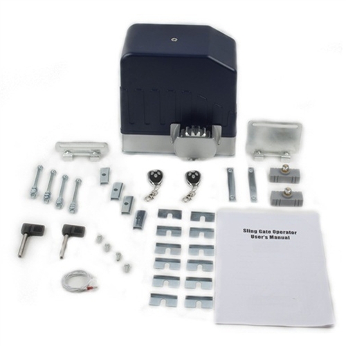
It comes with the kits that meet all my basic needs in my plan:
- Gate opener.
- Two (2) remotes.
- Mounting bracket.
- Anchor bolts.
- Screws and nuts.
- Gear lock/unlock key.
- 20 ft (3.3 ft x 5 pcs) linear gear rack.
Other specs all look fine to me:
- Opens gates weighing up to 1600 lbs. — Mine won’t be more than 300 lbs.
- Opens gates up to 55 ft. in length. — Mine is about 12 ft in length.
- Soft starting / stopping
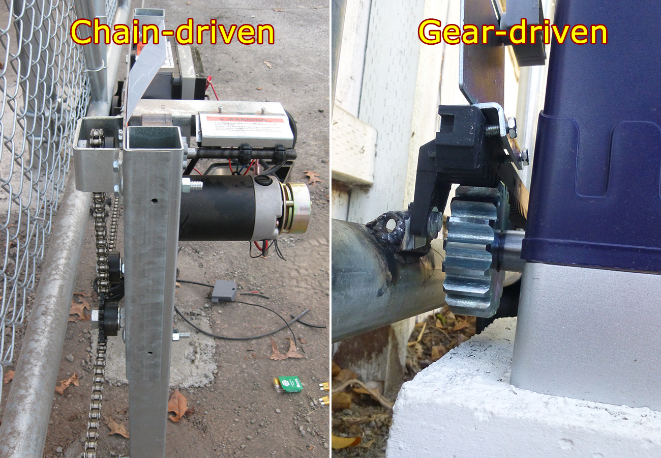
Gear-driven vs chain-driven
Chain-driven is the most common way to drive a sliding gate, it’s relatively cheaper and easier to install. However, gear-driven mechanism produces quieter and smoother transition. Plus, the linear gear rack looks more attractive than the sagging chain.

Receiving the packages
The first impression upon receiving the packages were heavy, both for the AR1450 opener and the nylon gear racks!

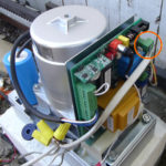
Don’t worry if you couldn’t find the remotes, they were actually hiding inside the opener’s plastic cover. Removing the plastic cover will expose the key components: the giant motor taking most of the space, the circuit board leaning against the motor, magnetic sensor and capacitor. It is not necessary to understand what they are. All you need to do is to wire your power cord to the connector shown in the photo below.
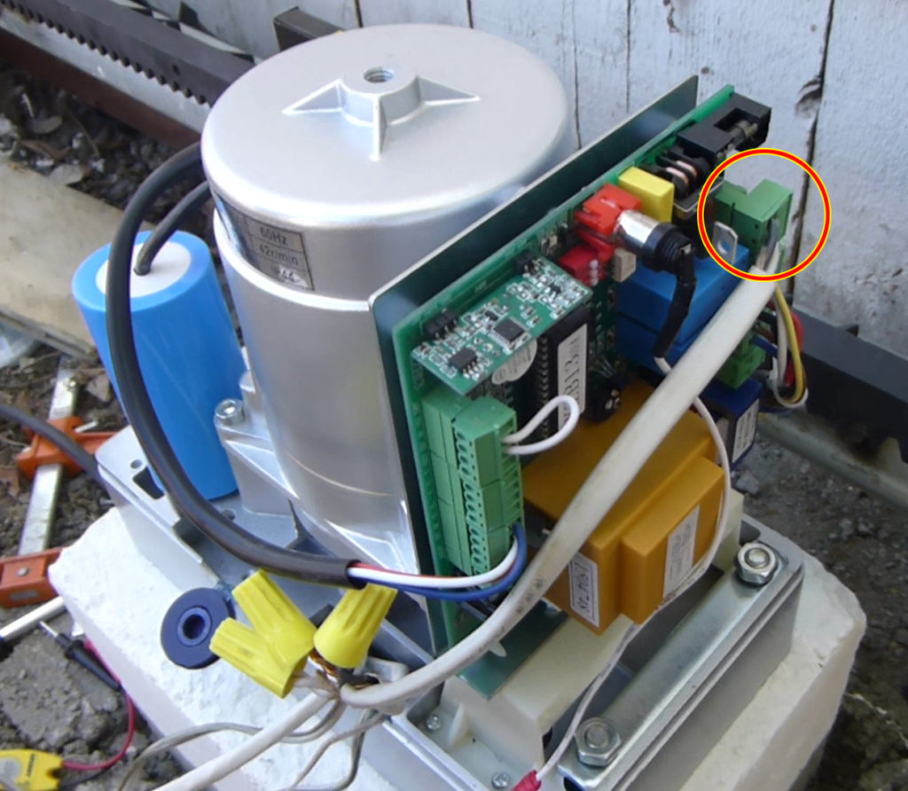
As soon as you get power cords connected correctly, the indicator on the circuit board will light up, and you can immediately control your opener with the provided remote! For tweaks like changing open/close direction, increasing/decreasing force or enabling pedestrian mode, you will need to dig a little deeper into the manual. Other than those, the gate opener almost requires zero effort on the electrical setup. Most of my work, however, was spent on the masonry work — taking measures, assembling mold and pouring concrete for the opener’s base.
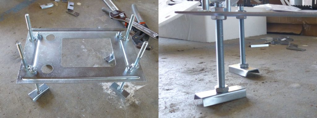
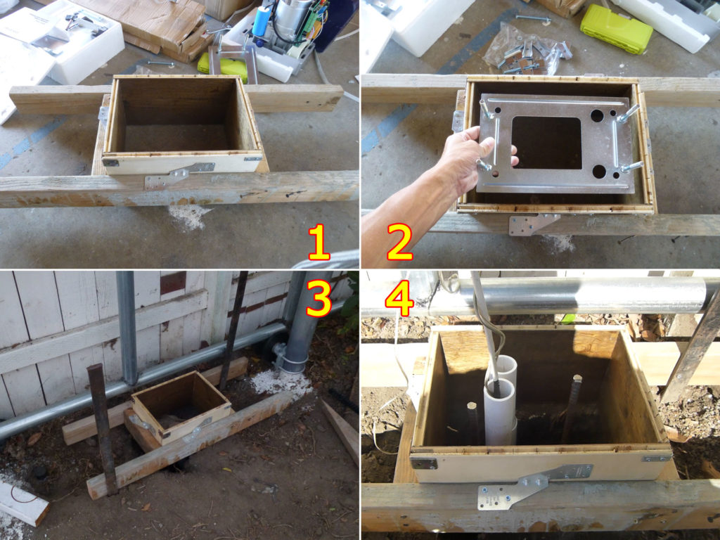
Assemble the mounting base and concrete mold
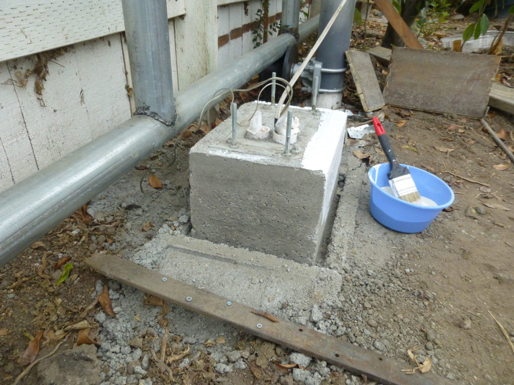
It took me quite sometime to figure out how to assemble the metal mounting base for the gate opener as the manual didn’t seem to be very helpful on this topic. The assembled mounting base looks like a mini oil rig: four anchors shown as below were to be buried in the concrete pouring to produce strong clamping force. Another set of bolts that go straight up are for the gate opener.
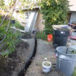
If you recall my last post about trenching, you’d probably have noticed that I dug a pretty big hole where the PVC pipe terminated. That hole was actually prepared for the gate opener. A rock solid base made by concrete is very important for the gate opener to provide enough force to move the gate. The hole was about 2ft wide by 2ft long, 1.5ft deep. Since the gate opener was measured to be installed at 8″ above the ground, I made a mold of the same height with width / length at about 1′ / 1’4″. Mold was then installed on the site with proper bracing and supporting to receive concrete.
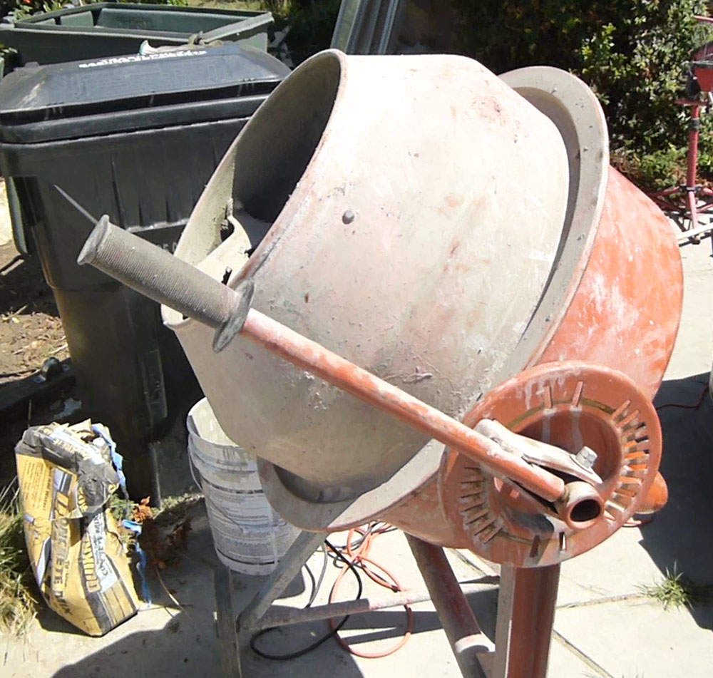
After I acquired a cement mixer (shown below), my concrete pouring work became so much fun! Before that, I was basically mixing it with shovels….worked fine but not easy. I depleted fours bags of 60lbs concrete mix to fill up the mold for the gate opener base pad. So total 240lbs, Heavy!!! Considering the force the motor is going to push on the gate, the heavier base really pays off.
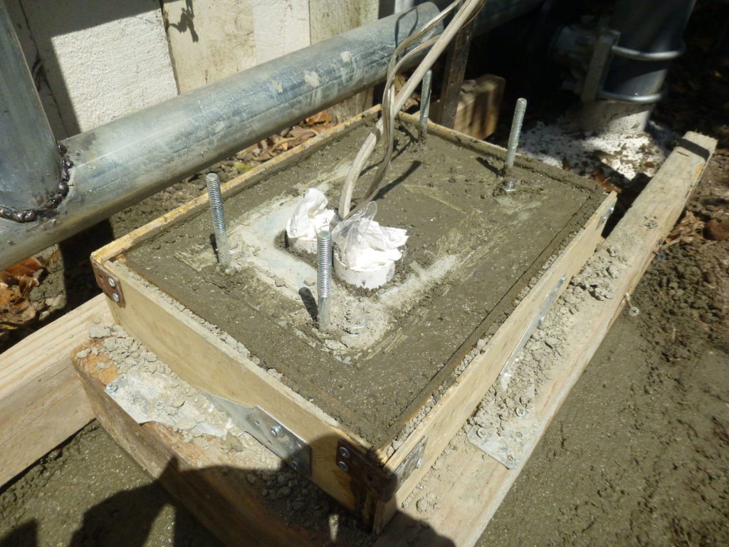
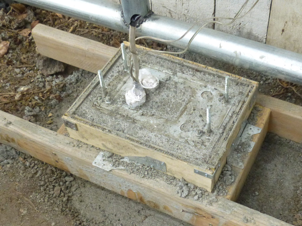
After I removed the mold, I painted the concrete base with wall sealer. Totally unnecessary, but I just happen to have it around. So why not?
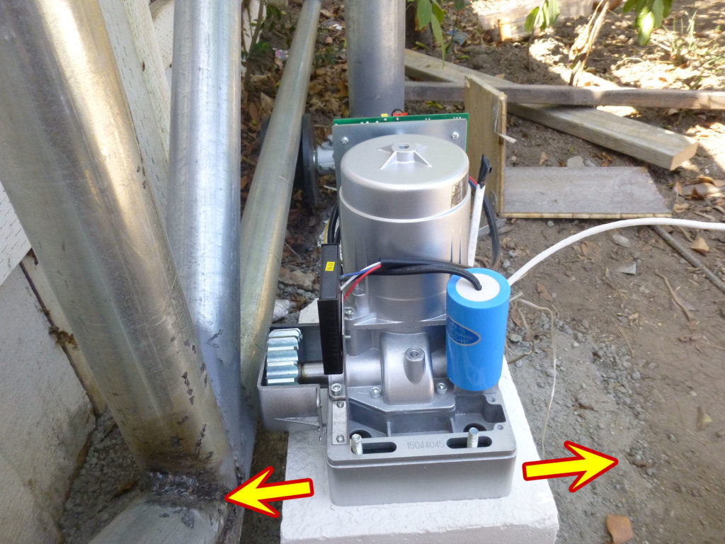
Now the concrete pad is ready to receive the gate opener. Make sure the opener is not too far nor too close to the gate frame. Measure the distance by roughly placing a nylon gear rack on the gate. When you are happy with the position, lock the opener with nuts provided. Make sure the opener is tightly secured on the mounting base.
Mounting the gear racks
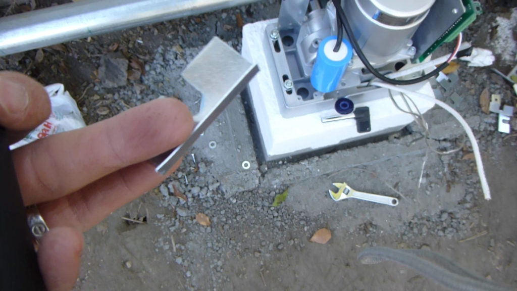
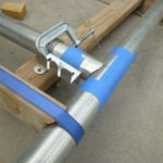
If my gate were composed of square metal tubes, it would be fairly easy to mount the gear racks — just to place the racks flush against the frame and use self-tapping metal screws to fasten them. However, circular pipes like mine doesn’t provide any flat surface to be flush against. I would have to “create” some.
Looking back into the gate opener kits, I noticed one type of parts that I never realized what to do with before. The small metal bracket shown in the photo below is actually a piece of perfect gadget to “create” such flat surface for the purpose of mounting the gear racks on round pipes.
In order to “create” such flat surface, I would need to weld this bracket on to the pipe. Since I welded the whole gate frame together, this small task wouldn’t be a challenge for me any more.
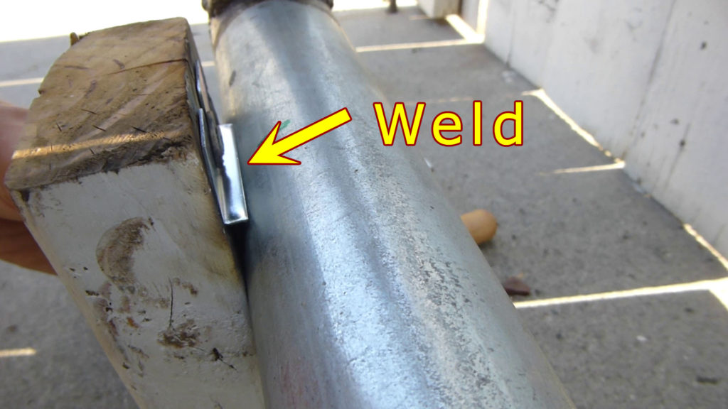
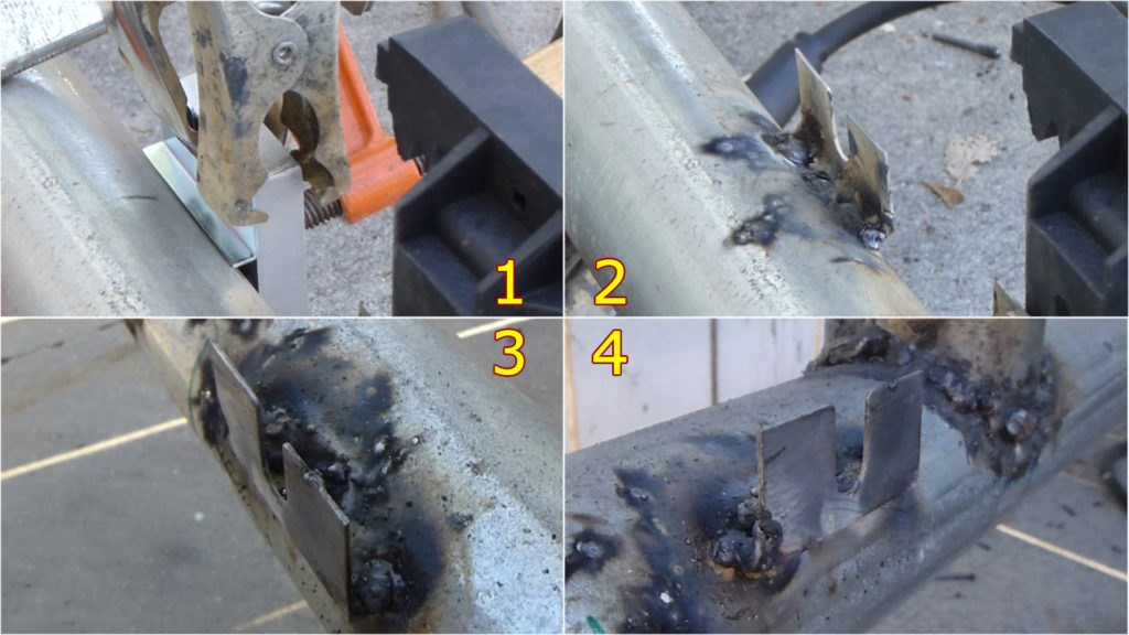
I still don’t know if I am making correct use of those brackets, but they do look perfect for this purpose. The bracket has a open slot in the middle, so I could easily adjust the height of the gear rack. Here is the final assembly of the gear racks on those brackets, and I connected four racks together to make a 12-foot long continuous gear rack.
Related posts:
- DIY, how to build your own cantilever sliding gate (8) – Mount the fencing board!
- DIY, how to build your own cantilever sliding gate (7) – Install the gate opener
- DIY, how to build your own cantilever sliding gate (6) – Run the power cord through underground conduit
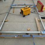
- DIY, how to build your own cantilever sliding gate (5) – Weld the galvanized pipes into a gate frame
- DIY, how to build your own cantilever sliding gate (4) – Notching steel tube / galvanized pipe for cheap!
- DIY, how to build your own cantilever sliding gate (3) – Set the posts using 4″ diameter galvanized pipe by only one man
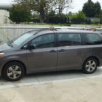
- DIY, how to build your own cantilever sliding gate (2) – Transport the oversize pipes on a family minivan
- DIY, how to build your own cantilever sliding gate (1) – Make a plan
Leave a Reply